Posts

All Fair and Prime

Image
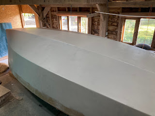
 Fairing the hull and Priming After quite a long time away from the boat due to work commitments and Freddie heading across the Atlantic I'm finally back in the barn and persevering with the fun of filling, fairing and lots and lots of sanding.  We decided to fair and prime the hull before turning over as having painted a fair share of boats before, working underneath is even less fun! We left a strip of around 150mm from the gunnel down the topsides for hull to deck joint. I've tried really hard to limit the amount of filler I've put on the boat, it being made of flat panels there isn't lots of curvature that needs to be smoothed over, and more filler equals more sanding, more cost and a lot more time. The majority of filler I've been using is epoxy with micro balloons and some colloidal silica mixed to a nice thick peanut butter consistency. This was applied with a nice long straight edge and plastering spatulas. Having sanded this back, I then used some quick cur

Glassing the Hull

Image
 Glassing the Hull This was a big day and a major milestone in our build! Having blended, rounded and faired the planking joints as much as we could we taped all of the joints using 2 layers of 600gsm triaxial tape, during this we sealed all the plywood with epoxy, just rolling it on with a paint roller so that when we laminated the bare plywood wouldn't pull resin out of the laminate and leave it dry. We covered the hull in peel ply and let this cure and then gave it a light sand up to remove any amine residue not caught by the peel ply and give it a key for the main lamination. We completed the main lamination in a single day, having drafted in a couple of extra helpers. We went for 600gsm woven roving to give a total laminate weight of 1200gsm - slightly over the requirements.  We worked on a basis of a glass to resin ratio of 2:1 so for every m^2 of fibreglass we needed 1.2kg of resin. We had someone measuring and mixing small batches constantly as the three of use were laminat

Planking

Image
 20/02/2021 Delayed by a week because of a spell of weather too cold to glue in, very happy to have completed this stage though.  Some of the stringers needed to be shaped first, as did the end of the keel floors.  I attached the planks in three steps: 1. topside and inner bottom; 2. chines; 3. outer bottom. This was a mistake, not too sure why I did it that way. B&B designed the kit to be assembled topside-chine-bottoms. It wasn't too much of a drama, but would probably have made shaping easier and quicker, the main issue was with the forward chine planks. Having only two hands, it would have been much easier to clamp the top of them onto the stringer, not possible with the bottom plank already glued in. Taking the planks on and off to make alterations and then glue made it a bit of a bastard.  I did not use the butts to join the planks together as it seem cumbersome and unnecessary, but have now been persuaded to fit them later to reduce flex at the joins. Freddie

Stringers on Frames

Image
 05/02/2021 Lots of adjustments, shaping, swearing and patience to get the stringers in place. Working in a relatively balanced fashion so as not to put uneven pressure on the frames and distort the symmetry. Once all the stringers had been dry-fitted and screwed into place, I mixed up a very thick mix of glue and stuck it all together.  Freddie

Frames on Strongback

Image
 25/01/2021 She's starting to look like a boat! Frames E, D and D1 went up in a similar fashion to T and A, so the next step was to slot the bunk sides into A and D1 to position S, C and B. With hindsight it may have made sense to mount D1 first, and then A and the bunk side together, but instead we cut the tabs on the bunk sides short and it worked out ok. Extra strength will be added in the filleting, but probably not necessary. The only consideration we found was to square off some slots and bevel some edges.  After the bunk sides we moved to the cockpit sides. securing them onto A and T. The top of S was then dropped into the slot in the bunk sides and found a perfect line running down the cockpit side and to its timber on the strong back. Move B and C into position and all frames are mounted.  We also put the knee and stem into position (missing from the photos). Relatively strait forward process from the B&B plans.  Freddie

Keel floors

Image
 23/01/2021 Timber was bought pre-cut to the 60*70 required and in a mix of lengths roughly the right size. Using the full size stencil provided by B&B; I transferred the angles notches for the stringers. The rest follows as pictured.  Freddie

Strongback

Image
 22/01/2021 Great day putting the strongback together. The plans from B&B were invaluable, using the inside after corner as datum took away issues with not all 6*2 being created equal. We only marginally went rogue, in part due to some errors with saw cuts, partly an error with the timber order, but the important distances between the frames were kept accurate.  Our concrete floor isn't too level, so the height of the frame needed to be adjusted with wedges. Once the upright timbers are installed they act as feet to keep it in place, their end height not being particularly important.  Also managed to put up frames T and A. A string-line down the centre of the framework, laser-level on top of it, set the height for the top of the frame, make it all line up and screw it in. Some blocks on the posts for the frames to sit on are helpful.  Freddie